
Machining for woodworking is divided into three control methods. The entire computing process is controlled by computers. When the engraving machine is operating, the computer is in a working state, which means that other typesetting work cannot be performed, resulting in waste products.The engraving machine can typeset while working, but the computer cannot be turned off, reducing the waste caused by faulty computer operation.It is also possible to transmit data via the USB port, since the system has a memory capacity of more than 32M, and the file can be separated from the computer after saving. By turning off the computer or doing other typesetting, productivity can be improved.
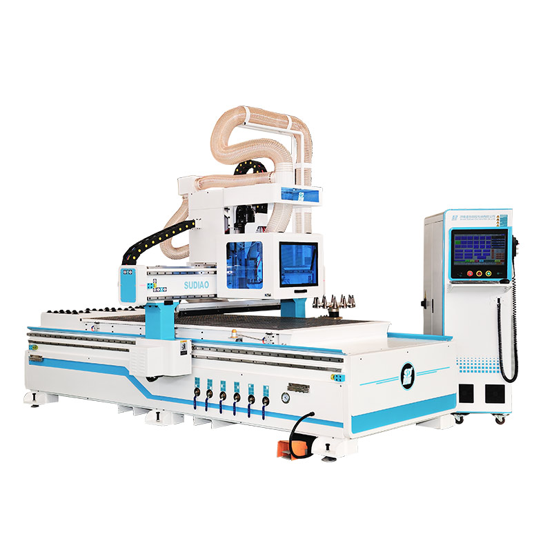
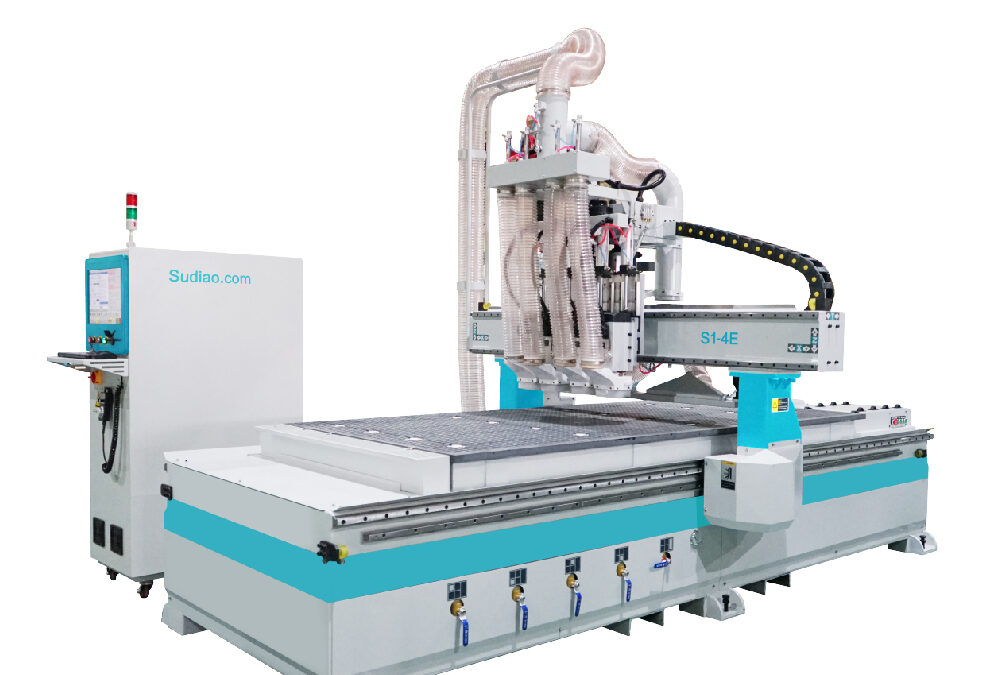
Overview of woodworking engraving machine
Mainly used for woodworking, crystal, copper, aluminum, etc. make it more aesthetically pleasing. There are many types and brands of woodworking engraving machines, resulting in uneven prices.
The style is customized according to customer needs. It can be applied to wood industry, advertising signs, furniture manufacturing, toy and gift manufacturing, decoration industry, PCB manufacturing, etc.
Features
The following is a detailed introduction of the key functions of the woodworking engraving machine:
- Start to pause: When the processing file has been loaded, if the system is in the idle state, press this key, the system starts to run the processing program. if the system is already in the processing state, press this key, the system pauses the processing.
- Stop: stop the current operation. If the system is in the processing state, press this key to stop the processing; if the system is in the floating tool setting state, press this key to stop the floating tool setting.
- Continue at breakpoint: If the system is in the processing pause state, press this key, and the system will continue processing at the breakpoint.
- Continuous: switch the user data input to manual continuous.
- Spindle switch: If the spindle has been turned off, press this key to turn on the spindle; otherwise, turn off the spindle.
- Return to origin: press this key, the system executes the command of returning to the origin of the workpiece.
- ×1: Press this key to set the jog step to 0.01mm.
- ×10: Press this key to set the jog step to 0.1mm.
- ×100: Press this key to set the jog step to 1mm.
- X+: Move the tool to the positive direction of X axis. If it is in the state of continuous jogging, jog continuously in the positive direction of the X axis; otherwise, move forward one step in the positive direction of the X axis according to the current step size. Note: If it is in continuous jogging state, single press this key, the tool will jog continuously at low speed manually;
- X-: Move the tool to the negative direction of X axis. The moving speed, step length and key combination are the same as the description of X+ key.
- Y+: Move the tool to the positive direction of the Y axis. The moving speed, step length and key combination are the same as the description of X+ key.
- Y-: Move the tool to the negative direction of Y axis. The moving speed, step length and key combination are the same as the description of X+ key.
- Z+: Move the tool to the positive direction of Z axis. The moving speed, step length and key combination are the same as the description of X+ key.
- Z-: Move the tool to the negative direction of Z axis. The moving speed, step length and key combination are the same as the description of X+ key.
- Shift: Pressing this key alone does not have any function, only when this key is pressed in combination with other keys has the corresponding function; please refer to the description of other keys for the type of combination.
- Knife setting: the second key from the left in the fifth row of the dedicated keypad. Press this key, the system will perform floating tool setting.
- F-: Press this key to reduce the feed rate.
- F+: Press this key to increase the feed rate.
Tool selection
- The basis for choosing a milling cutter
- The nature of the material being cut: The objects of wood cutting are solid wood and wood composite materials. Solid wood can be divided into soft wood, hard wood and modified wood, etc.; wood composite materials include laminated veneer, plywood, particleboard, oriented strand board, large particleboard, gypsum particleboard, cement particleboard, hard fiberboard, medium density Fiberboard, high-density fiberboard, blockboard, laminated wood, etc.
- Cutting direction: When cutting solid wood, according to the direction of the blade relative to the wood fiber, the wood cutting is divided into longitudinal, transverse, end and longitudinal end, longitudinal and transverse and transverse end cutting.
- Tool rotation direction and feed direction: According to the rotation direction of the tool axis of the machine tool and the feed direction of the wood workpiece, determine the inclination direction of the blade on the tool.
- Tool and workpiece stability: The stability of the tool and the workpiece during the cutting process includes several aspects. The stability of the workpiece refers to the smooth feeding of the wood workpiece during the cutting process without jumping. The measures taken to strengthen the stability of the workpiece mainly include reducing the center of gravity of the workpiece and increasing the contact area.
- Processed surface quality requirements: The surface quality of wood workpieces includes surface roughness, geometric dimensions and shape and position accuracy.
- Selection of woodworking milling cutters
- Determine the main technical parameters of the milling cutter: the outer diameter of the tool, the machining thickness, and the center hole diameter. Other technical parameters: the number of teeth, the direction of rotation, the speed of rotation, the feed speed, the clamping method, and the material of the teeth.
- Select the structural form of the milling cutter: According to the nature and requirements of the cutting object, comprehensively consider the technical and economic aspects to select the integral milling cutter, the welding integral milling cutter, the assembly milling cutter and the combined milling cutter.
- Selection of the rotation direction of the milling cutter: The rotation direction of the milling cutter is determined according to the rotation direction of the main shaft of the processing machine and the relative position of the cutter shaft and the feed workpiece. Whether it is an integral milling cutter or an assembly milling cutter, the cutting edge is relative to the milling cutter. The inclination of the radius determines the direction of rotation of the milling cutter.
- Selection of the cutting amount of the milling cutter: The cutting amount of the milling cutter includes the cutting speed of the milling cutter, the feed rate of the workpiece and the milling depth. The cutting speed of the milling cutter depends on the milling cutter speed and the radius of the milling cutter. The feed rate of the workpiece depends on the requirements for the quality of the machined surface. The surface roughness of the workpiece to be cut depends largely on the feed per tooth of the milling cutter during the cutting process. If the feed per tooth is too large, the machined surface is too rough, and the feed per tooth is too small, and the machined surface will burn. Therefore, the feed per tooth of the milling cutter must be appropriate.
- Stability of milling cutter operation: The stability of milling cutter operation is the basis for ensuring machining accuracy and surface quality. This includes two aspects: one is that the milling cutter vibrates due to the excitation of external force during the cutting process; the other is that the milling cutter is deformed under the action of external force.
- The safety of milling cutter processing: The safety of milling cutter processing includes milling cutter rotation speed limit, chip thickness limit, profile height limit of forming milling cutter, and assembly milling cutter blade thickness and protrusion limit.
Wood cutting is characterized by high-speed cutting. The rotation speed of the milling cutter is more than 3000rpm. High-speed cutting brings high production efficiency and smooth surface quality to wood cutting. At the same time, it also brings a series of safety problems. Therefore, when the spindle speed of the milling machine tool reaches 9000rpm, except for the shank milling cutter with a tool smaller than 16mm, the use of the assembled milling cutter should be prohibited. Strict flaw detection inspection. The chip thickness limit is a necessary measure to ensure that the milling cutter is severely overloaded due to the excessive feed rate of the milling cutter.
For the forming milling cutter, the height value of the forming profile is closely related to the clamping method of the milling cutter, the thickness of the cutting workpiece, and the diameter of the milling cutter. After the thickness of the cutting workpiece, the diameter of the milling cutter and the central aperture are determined, the height of the milling cutter profile reflects the strength and stiffness of the milling cutter itself, as well as the ability to withstand cutting resistance. Therefore, the height of the profile must be limited to ensure the safety of the milling cutter. The clamping of the blade must be considered when designing the assembled milling cutter body. Whether it is a cylindrical cutter body or a disc type cutter body, the clamping form of the blade must ensure that it can provide enough clamping force to resist the rotary centrifugal force.
Jinan Sudiao CNC Router Co., Ltd was An approved and registered enterprise by the Jinan Bureau of Commerce and Industry. A professional manufacturer engaged in research and development, design and production of the following machines: automatic labeling and cutting machine, customized cabinet intelligent nesting machine, CNC six-sided drilling machine, CNC panel saw, intelligent cabinet processing line, cabinet door moulding line, multiple six-sided drilling machines connections. We can plan and design the processing flow of your factory according to your demands. Contact Us
Main Products: